what is a butterfly valve
Leave a message
In industrial applications, valves, as core devices for controlling fluid flow, play a crucial role. With the advancement of science and technology, higher demands are being placed on valves, especially for valves used for specialized applications, which play an even more crucial role. Butterfly valves, as core components in the valve family, have gained widespread use across multiple industries due to their unique advantages. Pneumatic butterfly valves are the most widely used type. These devices, characterized by their simple structure, compact size, light weight, rapid opening and closing, and flexible operation, effectively control and shut off fluid flow. The recent development and maturity of computer and network technologies have enabled breakthroughs in butterfly valves in many areas. Butterfly valves play a vital role in industries such as water supply and drainage, petrochemicals, power generation, and metallurgy, as well as in civilian applications such as air conditioning and fire protection. With the continuous improvement of my country's economy, industrial development has entered a new stage. Therefore, in-depth research on the working mechanism of butterfly valves is crucial for a more comprehensive understanding and application of these devices, as well as for improving industrial production efficiency and safety.

How does the butterfly valve disc achieve opening and closing?
(I) Disc Structure
The disc of a butterfly valve is generally designed as a thin, circular plate. This design ensures relatively low resistance when moving through the fluid. There are many ways to connect the disc to the valve stem, including pin and key connections. To prevent the disc from falling off or being damaged, a retaining nut is used to tighten the bolts to maintain its position, and a spring is used to maintain the disc at a certain angle to achieve a seal. Using these connection techniques, the disc is securely fixed to the valve stem and rotates synchronously with the stem, achieving the desired opening and closing effect. Because the pin and key are made of rigid materials, they can be easily welded or riveted. For example, in some small butterfly valve designs, the use of a pin connection not only ensures a stable connection but also simplifies installation and disassembly.
(II) Actuation Method
- Manual Actuation
Manual actuation is considered one of the most common actuation methods for butterfly valves. However, this structural design is prone to interference, leading to problems such as instability or failure. Among these, the handle actuation method is simple and intuitive. The operator rotates the handle to rotate the valve stem, thereby rotating the valve disc. Ergonomic principles are often taken into account when designing the handle length and shape, making it easier for the operator to apply torque. This transmission method also avoids the noise associated with traditional mechanical connections. The worm gear drive is particularly suitable for applications requiring high torque. It leverages the worm gear's transmission ratio to amplify a relatively small input torque, effectively actuating the valve stem and disc. For example, in some large butterfly valve designs, due to the heavy weight of the disc, the use of a worm gear can effectively reduce operator stress.
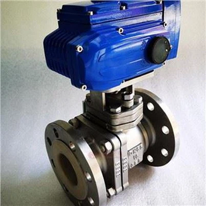
- Electric Drive
Electric drives use an electric actuator to convert electrical power into mechanical force, which in turn actuates the valve stem and disc. Electric actuators are a type of actuator in hydraulic systems and play a crucial role in hydraulic control systems, directly impacting overall system performance and reliability. Electric actuators typically consist of multiple components, including an electric motor, a speed reducer, and a position sensor. The electric actuator is connected to the valve via a coupling mounted on the motor. The electric motor, as the power source, further rotates the valve stem after being decelerated and torque-increased by a speed reducer. When the valve opening needs to be adjusted, a position sensor detects the relative displacement of the valve disc. This position sensor provides real-time information on the valve disc's position, enabling precise control of its opening and closing angles. With the advancement of electronics, computers, communications, and servo control technologies, traditional valve control systems are no longer able to meet the requirements of modern industrial production. Electric actuators are gradually replacing mechanical actuators and becoming the mainstream valve technology. In some highly automated industrial systems, electrically driven butterfly valves can be linked with other equipment for improved production efficiency.
- Pneumatic Actuation
The operating principle of pneumatic actuation is that compressed air drives a piston, which in turn drives the valve stem and disc to open and close. Pneumatic actuators operate by controlling valves to achieve various movements under certain conditions of air pressure and flow. The main components of a pneumatic actuator include a cylinder, piston, and spring. They can be used to control the opening and closing of valves and other mechanical equipment. When compressed air enters the cylinder, it drives the piston, overcoming the resistance of the spring and causing the valve stem and disc to rotate. During the opening and closing process, the reciprocating motion of the piston creates a pressure differential, causing the disc to open or close. When the compressed air is exhausted from the cylinder, the spring's elasticity causes the piston to return to its original position, closing the disc. Therefore, pneumatic actuators are a typical type of actuator. Pneumatic actuation technology is favored for its fast response, agility, and high safety, particularly in applications with strict fire and explosion protection standards.
(III) Operation Process
The butterfly valve disc typically rotates between 0° and 90° from fully closed to fully open (or vice versa). In the closed position, the disc fits tightly against the seat, interrupting fluid flow. When fluid enters the pipeline, due to the valve's structural characteristics and the inherent gravity of the medium, some liquid or gas may be trapped on the disc, resulting in loss of flow and pressure. As the disc begins to rotate, the gap between it and the valve seat gradually widens as the rotation angle increases, simultaneously expanding the area of the fluid passage. When the valve body is open, the pressure differential causes fluid to leak outward along the valve stem and ultimately reach the sealing surface, allowing fluid to flow smoothly into the valve cavity. When the disc rotates to a specific angle (for example, 45°), the area of the fluid passage expands to a certain level, allowing fluid to flow more smoothly. After the valve is opened, the disc continues to rotate due to pressure and spring force until a negative pressure zone is created in the valve body, allowing fluid to enter the fluid passage and flow in that direction. When the disc reaches a 90° rotation angle, it becomes parallel to the direction of fluid flow. In this state, the fluid passage area reaches its maximum, minimizing fluid resistance and allowing fluid to flow through the butterfly valve at maximum flow rate. When the valve is open or closed, the disc continues to rotate under its own weight, generating friction that creates an annular gap between the valve body and the sealing surface, creating a negative pressure in this sealed cavity. The closing process is the opposite of the opening process. The valve disc gradually rotates back from 90° to 0°, and the area of the fluid channel gradually decreases from the maximum value to zero, eventually completely cutting off the flow of the fluid.

How does the fluid passage area change during the opening and closing of a butterfly valve?
(I) Closed State
When a butterfly valve is in the closed state, its disc and seat are completely in contact, forming a closed interface. This completely blocks the fluid passage, reducing its area to zero. When in the open state, a slight gap exists between the sealing surfaces, preventing liquid from flowing directly into the pipe. This sealing condition effectively prevents fluid leakage and ensures stable system operation. Furthermore, due to its excellent sealing and stability in the closed state, it is widely used in practical applications. For example, in water supply and drainage systems, a closed butterfly valve helps prevent backflow, thereby reducing potential damage to related equipment.
(II) Initial Opening
When the disc begins to rotate, a crack gradually develops between the disc and seat, causing the fluid passage area to gradually expand. Once the opening process reaches a certain point, the fluid flows out of the passage, forming a closed space. During this stage, fluid flow is significantly restricted, resulting in a slowdown in flow rate and a reduction in flow rate. When a certain rotational speed is reached, the fluid passage area rapidly increases. As the disc's rotation angle gradually increases, its gap also widens, leading to a corresponding increase in the fluid passage area. After reaching a certain speed, friction causes the disc to stop rotating, and the fluid passage area rapidly decreases to a very small value. At this point, the valve closes more slowly or even fails to open. For example, at a disc rotation angle of 10°, the fluid passage area may be only approximately 10% of that in the fully open state.
(III) Mid-Opening
As the disc continues to rotate, the fluid passage area rapidly expands. After reaching a certain speed, the fluid velocity slowly decreases and stabilizes. At this point, the fluid flow pattern undergoes a significant shift, with a significant increase in flow velocity and flow rate. When the velocity remains constant, the fluid passes through the butterfly valve in a turbulent flow pattern. As the fluid passage area gradually expands, the resistance encountered by the fluid as it passes through the butterfly valve decreases, thereby reducing energy loss. Furthermore, the increased disc rotational speed generates more bubbles in the fluid passage, which improves butterfly valve performance. For example, when the disc is rotated to 45°, the fluid channel area may already exceed 50% of its fully open state, allowing fluid to flow more smoothly through the butterfly valve.
(IV) Fully Open State
When the disc's rotation direction aligns with the fluid flow direction, that is, when the rotation angle reaches 90°, the fluid channel area reaches its maximum value. When the valve is closed or open, as the disc's rotation angle increases, the fluid velocity gradually decreases, while both pressure and flow rate increase and then decrease. At this point, fluid resistance is minimized and flow rate is maximized. When the valve body is in the closed position, fluid pressure is lowest and flow rate is highest. When the butterfly valve is fully open, it can meet the system's high-flow fluid transmission needs. Furthermore, due to its simple structure and easy operation, butterfly valves are widely used in the petroleum and chemical industries. For example, in the petrochemical industry, when large butterfly valves are fully open, they ensure efficient transmission of various media such as crude oil and natural gas.
(V) Reverse Changes During the Closing Process
During the closing phase, the change in fluid channel area is opposite to that during the opening phase. After a butterfly valve is opened, the fluid passage area continuously increases. As the butterfly valve begins to close, the disc gradually rotates, causing the fluid passage area to gradually decrease from its maximum value. While the valve opening remains constant, varying the distance between the valve body and bonnet can significantly change the fluid passage area. As the disc's rotation angle gradually increases, the fluid passage area decreases at a faster rate, and the fluid velocity and flow rate also gradually decrease. After the valve closes, fluid enters the valve body and forms a vortex zone, creating secondary flow and vortex cores, which hinder fluid flow. Finally, when the disc and seat are fully engaged, the fluid passage area decreases to zero, completely shutting off fluid flow.

How does a butterfly valve seal during operation?
(I) Sealing Structure
Common sealing methods for butterfly valves are categorized as soft seals and hard seals. Hard seals typically utilize a mechanical device made of metal or ceramic to forcefully seal the fluid. Their characteristic is that they minimize leakage without requiring additional power, making them widely used. Soft seals typically use rubber, polytetrafluoroethylene, or other materials as sealing rings. These materials offer excellent elasticity and sealing properties. In terms of sealing construction, the sealing surfaces of the valve seat and disc are typically designed with specific shapes and dimensions to ensure a tight fit between the sealing rings, resulting in excellent sealing performance. Soft seal glands are primarily made of plastic or nylon. In hard seals, metals such as stainless steel and carbide are commonly used as sealing components. Metal seals are a special sealing component made by pressing metal powder and containing a certain amount of metal particles. Through meticulous processing and fitting, metal seals achieve a metal-to-metal seal under the influence of medium pressure.
(II) Soft Sealing Principle
Under the influence of pressure, soft sealing materials may elastically deform, helping to fill the slight gap between the disc and seat, thereby achieving a sealing effect. Butterfly valves are a commonly used valve, with the internal medium being a gas or liquid. When the butterfly valve is closed, the pressure exerted by the disc and seat causes the sealing ring to elastically deform and tightly adhere to the sealing surface, preventing fluid leakage. Soft sealing materials are a new type of sealing component primarily used in the chemical industry to connect cryogenic containers and high-temperature, high-pressure equipment. Due to their excellent sealing properties, soft seals effectively prevent the leakage of small particles and liquids. Therefore, soft sealing materials are widely used in the petrochemical industry. However, soft sealing materials have relatively poor heat and pressure resistance in high-temperature and high-pressure environments, and are prone to aging and deformation, leading to sealing failure. Poor quality of the sealing material itself, or thermal expansion caused by large temperature fluctuations during use, can affect the soft seal and shorten its lifespan. For example, under high temperature conditions, rubber seals can become soft and melt, losing their original sealing function.
(III) Hard Sealing Principle
Hard sealing technology achieves a tight metal-to-metal seal under the influence of medium pressure through the precise machining and matching of the valve disc and valve seat sealing surfaces. The valve disc is made of cemented carbide and has a certain hardness. During the manufacturing process, the sealing surfaces of the valve disc and valve seat undergo multiple processing steps, including fine grinding and polishing, to ensure that the surface roughness and flatness meet the specified standards. The primary valve used in China today is the butterfly valve. Due to its simple structure and compact size, it is widely used in the chemical, petroleum, metallurgical, and power industries. When a butterfly valve is closed, the medium pressure forces the disc and seat to seal tightly together, forming an effective barrier to prevent fluid leakage. Because butterfly valves require significant opening force, they must be protected with a hard seal to prevent environmental pollution and safety hazards caused by fluid leakage. Hard seals, with their excellent resistance to high temperatures and pressures, can operate stably under harsh conditions such as high temperatures, high pressures, and severe corrosion. Currently, hard seals are primarily used in the oil and gas industry. However, compared to soft seals, hard seals offer slightly less sealing performance, require higher manufacturing precision, and are more expensive to produce.
(IV) Factors Affecting Sealing Performance
The sealing performance of butterfly valves is affected by a variety of factors, including medium pressure, temperature, and flow rate. This article analyzes the effects of medium pressure and temperature on the sealing performance of butterfly valves. When the pressure of the medium is too high, the sealing material may be deformed or damaged, resulting in the failure of the sealing function; when the temperature of the medium is too low or too high, the service life of the butterfly valve will be shortened. When the temperature of the medium is too high or too low, the working performance of the sealing material may be affected, resulting in a decrease in the sealing effect; when the flow rate is too fast, the sealing surface will be washed away, which will cause the sealing surface to wear more quickly, thus adversely affecting the sealing effect. In addition, the fluid in the valve body loses heat due to friction during movement, causing a large temperature rise on the valve disc surface. In addition, factors such as wear and corrosion of the valve disc and valve seat may also cause the sealing function to fail. Therefore, the valve disc, valve seat and valve core need to be inspected regularly. After long-term use, the sealing surface of the valve disc and valve seat may have defects such as scratches and pits. These defects may widen the sealing gap and increase the risk of leakage.

Conclusion
The operating mechanism of a butterfly valve includes several core elements, including the opening and closing of the disc, the change in fluid channel area, and the basic principles of sealing. A butterfly valve primarily consists of a valve body and disc. Its structure is simple, easy to manufacture, and convenient to install and maintain. The disc rotates via various drive mechanisms, enabling precise control of fluid flow. The area of the fluid channel fluctuates regularly during its opening and closing, affecting fluid flow. The sealing surface material is a key factor in ensuring valve sealing, and its structural form directly determines the contact between the fluid and the valve body. Both soft and hard seals have their own strengths and weaknesses, and sealing effectiveness is affected by multiple factors.
To ensure the correct selection, installation, operation, and maintenance of butterfly valves, a thorough understanding of their operating mechanisms is crucial. Because butterfly valves are typical throttling mechanisms, their structure is relatively complex, and in production, the valve opening must be adjusted to adjust flow in various situations. In order to ensure that the butterfly valve can work normally and improve the efficiency and safety of industrial production, we must select the appropriate butterfly valve type and sealing method according to the actual working environment, and install and operate it in strict accordance with relevant specifications. At the same time, regular maintenance and servicing are also required.