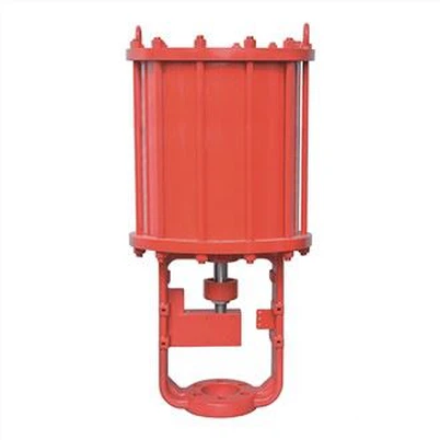
Inspection method of pneumatic actuator 1
Leave a message
Pneumatic valves are now more and more widely used in various industries, the technology of pneumatic actuators is getting better and better, the gap between domestic pneumatic actuators and imported pneumatic actuators is getting smaller and smaller, and there are more and more types. Introduce several inspection methods for pneumatic actuators:
1. Fix the pneumatic actuator on the calibration table, connect the air source, control air source and displacement detection connecting rod respectively; adjust the calibration table accurately;
2. Mechanical zero point calibration: input 4ma current signal (0%), the control gas signal should be 0.02mpa, at this time the cylinder piston stroke should be zero; if it is not zero, the zero point can be adjusted by adjusting the nut on the zero adjustment screw ( The zero point is higher than the tight nut); the zero point and span need to be adjusted repeatedly; the zero point error should be ≤1%;
3. Mechanical full-scale calibration: input 20ma current signal (100%), the control gas signal should be 0.10mpa, at this time the cylinder piston stroke should be the upper limit; if it is not the upper limit, you can adjust the tension of the range tension spring To adjust the range (the range is smaller, the tension spring is loosened, and the larger range is the tension spring); the zero point and the range need to be adjusted repeatedly; the full-scale error should be ≤1%;
4. Positioning the midpoint of the range: After the zero point and the range are adjusted, input a 12ma current signal (50%, 0.06mpa), and adjust the position of the connecting rod of the position transmitter to keep it perpendicular to the horizontal plane at this point;
5. Full stroke deviation calibration: input control gas signal 0.02mpa (0%), then gradually increase input signal 0.036 mpa (20%), 0.052 mpa (20%), 0.068 mpa (60%), 0.084 mpa (80%) , 0.1 mpa (100%), so that the piston travels completely, and the deviation of each point should be ≤1.5%;
6. Non-linear deviation test: input the control gas signal 0.02mpa (0%), then gradually increase the input signal until 0.10mpa (100%), and then reduce the signal to 0.02mpa (0%), so that the actuator can go full stroke , and record the stroke value corresponding to each increase or decrease of 0.008mpa signal pressure, the nonlinear deviation between the actual pressure-stroke relationship and the theoretical value should be ≤1%;