Comprehensive Analysis and Handling of Position Feedback Signal Anomalies in Single-Seat Control Valves
Leave a message
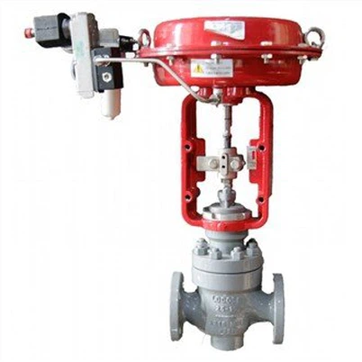
In industrial automation control systems, single seat control valves is a key driving element, the accuracy of its position feedback signals directly affects the stability of process parameters. When feedback signal is abnormal, a systematic troubleshooting approach is required to locate the root cause swiftly. Combining typical case and industry experience, this paper discusses the fault phenomenon, cause analysis and process in detail.
Classification Common Fault Phenomena
Complete loss of signal
- The DCS shows that the position of the valve remains the same over a long period of time (e.g. 0% or 100%).
- When valve operation manually, the feedback signal remains the same.
- Typical Case: chemical plant steam control valve are displayed on the DCS screen as completely closed, while the actual valve is ajar, causing uncontrolled steam flow and triggering interlock shutdown.
Abnormal Signal Fluctuations
- Feedback values fluctuates frequently near the setpoint (±5% or more).
- Periodic signal oscillations (e.g. every 2 seconds).
- Typical case: In pharmaceutical fermentation tank, feedback from temperature control valves oscillate between 45% and 55%, resulting in temperature control bias exceeding + -3°C.
Excessive Signal Deviation
- Actual valve position deviation feedback value exceeds process tolerance (typically >2%).
- Feedback showed the opening 90% and closing 15%.
- Typical Case: In the catalytic cracking unit of an oil refinery, the feedback signal of the reactor inlet control valve is 8% lower than the actual position, resulting in the failure of catalyst flow control.
Deep Causes Analysis
(A) Mechanical Structure Issues
1.Physical damage to Feedback Components
Poor contact due to Oxidized microswitch contacts (typical service life: 3-5 years).
Worn cam mechanisms leading to stroke (stroke) misalignment (e.g., 12° feedback lag due to wear of water control valve cam by power plant).
Bend feedback rods (usually impacted by lateral force on stem).
2.Transmission Component Failures
Too much clearance standard clearance <0.1mm mm) in valve position sensor gear trains.
Broken coupled elastomers (accelerated aging at temperatures greater than80°C).
Mismatch between valve stem and actuator pushrod (permissible deviation ≤0.5mm).
B) Power system Issuess
1.Signal Transmission Faults
Damage to the shielding cable results in 50Hz power frequency interference (for example, feedback from gas control valve of a blast furnace in a steel plant is affected by VFD interference with an amplitude of up to 3V).
Oxidized terminal blocks increases contact resistance (should be less than 0.1 omega).
Safety barrier failure causes signal attenuation (e.g., input 4-20mA, output only 2-10mA).
2.Positioner Performance Degradation
Dust accumulation in nozzle-flapper mechanisms (e.g., a petrochemical unit's control valve nozzle orifice in petrochemical devices reduced from 0.3mm to 0.15mm).
I/P converter linearity deviations (standard linearity <±1%).
Parameter drift in smart positioners (requires automatic adjustment every 6 months).
(C) Process Medium Impacts
1. Valve Plug Fitting
Media crystallization results in plug adhesion (for example, the control valve at urea plant is open at 30%).
The slag interferes with the valve seats (usually used at the start of a new plant).
Corrosive media corrosion stopper (average corrosion rate in chlor-alkali industry is 0.2 mm / year).
2. Fluid Dynamic Impacts
High-speed dielectric induces valve stem vibration (vibration30 design required for flow rate greater than 30 m / s).
Flash/cavitation damage to plug surfaces (noise level >85dB, needs to be assessed).
Excessive unbalanced forces overwhelming actuator thrust (calculated imbalance should be less than50% of actuator output).
Standardized Handling Procedures
(A) Initial field visits
1.Secure Isolation
Complete process interlock removal.
Close the upper and lower manual block valves.
Release the dielectric pressure of the valve into the atmosphere.
2.Visual inspection
Check feedback device casing for damage (protection rating ≥IP65).
Observe whether terminal blocks shows signs of overheating (temperature <65°C).
Verify that the Verify valve position indicator alignment is consistent with actual position.
(B) Power system testing
1.Signal Measurement
Measure positioner output in mm (normal: 4-20mA).
Check signal cable insulation resistance (> 5 M omega).
Measurement of grounding resistance (< 4 omega).
2.Component Testing
Verify locator performance using substitution method (spare parts requiring pre-calibration).
Compare the input/output of the safety barrier (error <±0.5%).
Test microswitch operating values (contact closure force <0.5N).
(C) Mechanical system disassembly
1. Actuator Inspection
Measure spring preload (standard ± 10%).
Check diaphragm integrity (leakage rate <1ml/min).
Verify pushrod straightness (deviation less than 0.1mm/m).
2. Valve body removal
Inspect valve plug/seat sealing surfaces (roughness ≤Ra0.4).
Measure valve stem straightness (allow bending <0.05mm/100mm).
Commuter cavity debris cleaning (residual particles < 0.5mm).
(D) System Integration Verification
1. Parameter Tuning
Adjust positioner gain (P value <50%).
Set deadband range (typically 0.5%-2%).
Optimize filter time constant (T >0.5s).
2. Functional testing
Conduct full trip testing (record actual stroke feedback deviation).
Dynamic response testing was performed under simulated process conditions (response time <2s).
Stability was monitored for 72 consecutive hours (fluctuation amplitude <±1%).
INTRODUCTION Preventive Maintenance Strategies
Regular Maintenance Programme
Quarterly visual inspection and cleaning.
Electrical performance tests are conducted every six months.
Dismantling maintenance and spare parts replacement annually.
Critical Component Management
Establish a spare parts life inventory (e.g. 3 years of microswitch life).
Pre-replacement of components with a design life of up to 80%.
Storage of strategic spare parts (e.g., positioner core modules).
Process Condition Optimization
Control the temperature of the medium to material limit (e.g., 316L stainless steel <450°C).
Limit media flow velocity (generally less than50m/s).
Install filters (mesh size ≥100).
Through the fault diagnosis methods and the standard processing procedure, the reliability of single seat control valve position feedback signals can be significantly improved. As a result of the programme, a refinery and petrochemical enterprise reduced the failure rate of control valve failure from 12 to 3, reduced unplanned shutoffs due to abnormal signals by 85% and increased overall efficiency of equipment by 18 percentage points. Practice has proved that establishing preventive maintenance system is key to ensure long-term stable operation of control valves.