Analysis and Countermeasures for Unstable Flow Control in Electric Single-Seat Control Valves
Leave a message
Electric single seat control valves has simple structure, good sealing performance and low leakage rate. They use an electric actuator to move the plug inside the valve seat, precisely controlling the flow of fluid and thus changing the flow area. However, in practical application, control valves often appears flow fluctuations, sluggish adjustment, overload and so on, which leads to the performance of control system to decline, and even causes production accidents. Therefore, it is of great engineering significance to analyze the causes of unstable flow control and formulate effective countermeasures.
Working Principles and Stability Influencing Factors of Electric Single-Seat Control Valves
2.1 Working Principles
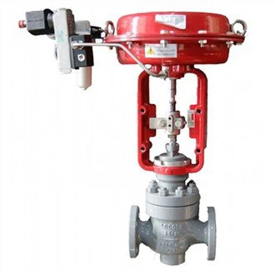
Electric single seat control valve is mainly composed of an electric actuator and valve body. The electric actuator receive control signals (usually 4-20 mA current signals) and drive the motor to rotate through a servo amplifier, then up and down the stem through a reduction gear mechanism to change the flow area between the plug and valve seat. Flow characteristics depend on the shape of the stopper (e.g. linear, equal percentage, rapidopening), while stability is influenced by a combination of mechanical, electrical, fluid and environmental factors.
2.2 Stability Influencing Factors
The stability of the control valve can be defined as the ability of the system to restore a set value after interference. Unstable flow control usually manifests itself as:
Periodic flow fluctuations (oscillations)
Sluggish regulation or overreaction
Persistent deviations between fixed and actual values
control valve Abnormal movement (e.g., jamming, vibration);
These phenomena may be the result of a single factor or a combination of factors and require systematic research.
3. Analysis of Causes for Unstable Flow Control
3.1 Mechanical Structure Factors
3.1.1 Wear of plugs and Valve Seat
After long operation, the contact surfaces between the stopper and valve seat can be damaged by friction, corrosion or corrosion, causing internal leakage. Internal leakage will change the flow characteristics of the control valve, resulting in the actual flow rate and set values between the deviation, especially in small openings.
3.1.2 Bent or Jammed Valve Stem
When the stem is bent or obstructed by a foreign object, the movement resistance of the stopper increases, resulting in an imbalance between the output force of the actuator and the frictional force of the valve stem. This can lead to sluggish movement or oscillation. In addition, overly tight or insufficiently lubricated valve stem packing of the stem filler may aggravate the blockage.
3.1.3 Spring Failure
Some control valves are reset or pretightened using springs. Fatigue or breakage of spring can cause displacement of valve plug position and affect flow control accuracy.
3.2 Electrical Control Factors
3.2.1 Actuator Failures
The motor, reduction gear and position sensor in the electric actuator Failures will directly affect the movement of the valve plug. For example, motor stalling, gear wear of reducer or inaccurate position feedback signals can lead to unstable control valve output.
3.2.2 Mismatched Servo Amplifier Parameters
Improper settings of the proportional (P), integral (I), and derivative (D) parameters the servo amplifier can cause oscillations in the system. Too high a P can lead to overregulation, too high an I can lead to sluggish regulation, and too high a D can make the system noise-sensitive, all of which can destabilise system.
3.2.3 Power Supply Fluctuations or Interferences
When the voltage of the power supply voltage is unstable or electromagnetic interference exists, the output power of the actuator fluctuates, causing the valve plug position to be adjusted repeatedly, causing the flow rate to oscillate.
3.3 Fluid Characteristic Factors
3.3.1 Changes in Fluid Viscosity
When the fluid viscosity is too high, the movement resistance of the plug increases and the reaction speed is slow. Conversely, low viscosity can lead to inertial overshoot. In addition, the viscosity change will also affect the flow coefficient (Cv value), leading to a deviation between the actual flow rate and the theoretical value.
3.3.2 Impurities in Fluids
Solid particles or fibrous substances in the fluid can block the flow gap between the stopper and seat, or between the valve stem and the guide sleeve, causing abnormal movement. Impurities will also accelerate wear and tear of the control valve, shortening its service life.
3.3.3 Fluid Pressure Fluctuations
Upstream or downstream Pressure fluctuations can alter the pressure differential of the entire control valve, thus affecting the flow rate. If the frequency of pressure fluctuations is close to the natural frequency of the control valve, resonance may occur, leading to severe flow oscillations.
3.4 Installation and Maintenance Factors
3.4.1 Improper Installation
If control valve is installed at an angle too large, the valve stem verticality to tolerance, or pipeline stress is not eliminated, the plug may be subjected to uneven force, causing blockage or vibration. In addition, insufficient front and back straight sections of the valve can also cause turbulence and affect the accuracy of flow measurement.
3.4.2 Inadequate Maintenance
Control valves that are not maintained for long periods of time may be slow due to scaling, rust, or lubrication problems. Periodic maintenance (e.g. cleaning, lubrication, replacement of seals) is essential to ensure the steady operation of control valves.
3.4.3 Calibration Errors
Inaccurate factory calibration or field tuning of control valve can lead to deviations between flow characteristics and set values. For example, incorrect calibration of flow coefficient (Cv value) or position feedback signals can lead to unstable control.
4 Countermeasures and Optimization Suggestions
4.1 Mechanical Structure Optimization
Periodically inspect and replace Worn Parts: Develop a regular maintenance schedule for control valves, focusing on inspecting for wear the valve plug and valve seat sealing surfaces and replacing damaged parts in a timely manner. For high frequency tuning conditions, consider the use of hard carbide or ceramic-coated valve plugs to improve abrasion resistance.
Improved stem design: Reduce the risk of blockage by adopting abending resistant stem structure (e.g. hollow stem or rib designs) and ensuring appropriate clearance between valve stem and guide bushing. Regularly lubricate the valve stem and check the tightening force of the packing to avoid overtightening or overtightening.
Spring Preload Adjustment: For control valves that rely on spring reset, the the spring preload should be regularly checked and adjusted to meet the design value to ensure that valve plug positioning is accurate.
4.2 Improvements in Electrical Control
Fault diagnosis and repair of actuator: using motor current monitoring, position feedback signal analysis and other methods to determine actuator fault points, timely replacement of motor, reduction gears or position sensors. For motor with frequent stall, overheating protection should be installed.
Servo Amplifier Parameter Tuning: the critical proportioning method or attenuation curve method is used to adjust the PID parameters to ensure that the system responds quickly and does not overshoot. For complex operating conditions, adaptive control algorithms (e.g., fuzzy PID) is introduced to improve robustness.
Power Supply Quality Enhancement: installing voltage stabilizers or isolation transformers in the supply system of control valve to reduce the impact of voltage fluctuations. In addition, signal cables are shielded and layed separately to avoid electromagnetic interference.
4.3 Fluid Characteristic Adaptation
Fluid Pretreatment: Install filters or separators in front of the control valve to remove solid particles or fibrous substances from the fluid. For high-viscosity fluids, heat tracing devices should be installed to reduce viscosity or control valves with the same flow characteristics should be selected to improve performance of small openings.
Pressure Stabilization Measures: install buffer tanks or pressure stabilizing valve before and after control valve to reduce the influence of pressure fluctuations on flow rate. For systems with high resonance risk, the natural frequency is adjusted by changing pipeline stiffness or increasing damper.
4.4 Standardization of installation and maintenance
Standard Installation Procedures: follow control valve installation instructions to ensure the valve stem verticality, length of front and back straight line of valve, and elimination of pipeline stress in accordance with standard. For vertically installed control valves, support brackets shall be installed to prevent valve stem bending.
Periodic Maintenance Plan: Develop a detailed maintenance plan for control valves, including cleaning, lubrication, seal replacement and performance testing. For control valves under critical operating conditions, keep spare valves handy for quick switching and maintenance.
Accurate Calibration and alignment: Calibration of the control valve on site using a high-precision flowmeter to ensure that flow coefficient (Cv value) corresponds to the set value. In addition, position sensor calibration tools used to adjust feedback signals to eliminate linear errors.
5 Conclusion
The instability of flow control of electric single seat control valve is the result of multiple factors, which require systematic analysis from mechanical structure, electrical control, fluid characteristics, installation and maintenance. By optimizing valve plug and valve seats design, improving actuator performance, adapting fluid characteristics, and standardizing installation and maintenance procedures, the stability of control valves flow control can be significantly improved. In addition, the introduction of intelligent diagnostics (such as vibration analysis and current monitoring) for fault prediction represents an important development direction of future control valve maintenance management. Engineers and technicians should combine the above measures with the specific operating conditions to ensure the long-term stable operation of control valves and provide security for the safe and efficient production process.