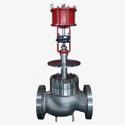
Fault Diagnosis and Handling of Single-Seat Control Valve Actuator Malfunctions
Leave a message
Single-seat control valves is a key part of industrial automation control systems, and actuator malfunctions is a common problem. Such failures may result from factors related to air supply, electrical systems, mechanical structures or control signals, directly affecting the stability of industrial processes. Based on actual cases and industry experience, this paper summarizes the process and solution of fault diagnosis process.
The Core Logic of Fault Diagnosis
The diagnosis of actuator malfunctions should follow the principle of ``first outside, then inside, first gas, then electricity, first easy and then difficult ''. The process is divided into four steps: air supply system inspection, electrical signal verification, mechanical structure test and control module diagnosis.
1.Air Supply System Inspection (Pneumatic Actuators)
Typical Fault Phenomenon: The actuator is inactive and air supply pressure gauge reading is zero or fluctuating.
Diagnostic steps:
Air Supply: Check that the main air supply pressure meets the valve's rated requirements (typically 0.4–0.7 MPa) and that air supply valve is fully open. At one chemical plant, a freeze in the air supply pipelines caused the collective failure of all control valves during winter.
Pipeline Leak Detection: Apply soapy water at the connection of air supply pipeline, and focus on the detection of filters, pressure regulators and solenoid valves. A steel mill discovered a small sand hole near the exit of the pressure regulator, causing pressure to drop to 0.2 MPa; normal operations resumed after the replacement.
Execution air tightness test: disconnect the actuator from the valve body, manually operate the positioner's output signal, and observe whether the actuator stem moves. If not, take the diaphragm apart to inspect for damage (common with equipment older than 5 years).
2.Electrical Signal Verification (Electric Actuators)
Typical Fault Phenomenon: The actuator's power light is on, but the signal is off, or the control module displays the alarm code.
Diagnostic steps:
Power quality testing: The the actuator's input voltage is measured using a multimeter to ensure that it is within the rated range (e.g. AC 220V ±15%). One power plant found that the actuator was often restarted due to voltage fluctuations.
Signal Line Troubleshooting: check the opening or short circuit of the 4–20 mA control signal lines, focusing on problems such as oxidized terminals or shield damage. A pharmaceutical company has resolved an actuator misoperations caused by signal line interference parallel to a power cables.
Control Module Diagnosis: Verify module functionality using comparison and interchange methods. A petrochemical company quickly solved actuator oscillation issues of actuator by replacing a positioner module.
3. Mechanical Structure Testing
Typical Fault Phenomenon: The actuator moves, but the stem does not, or movements slowly.
Diagnostic steps:
Valve Stem Jamming Resolution: Remove valve body and check for foreign objects (such as solder slag, rust) that hinder core. A new energy company has successfully used high-pressure air backflushing to remove a blocked valve core.
Transmission Component Inspection: check if the connecting pin between actuator and valve stem is broken. A paper mill discovered fatigue fractures in connecting rods due to prolonged vibration.
Fill adjustment: If valve stem movement resistance is too great, slightly relax packing gland nuts (while avoiding leakage). A food processing enterprise solves the problem of stem adhesion by adjusting packing tightness.
4. Optimization of control parameters
Typical Fault Phenomenon: Frequent oscillation or slow response of the The actuator.
Diagnostic steps:
PID Parameter Tuning: Adjust proportional frequency band, integral time, and derivative time using empirical or critical proportional methods. The chemical plant increased the ratio band from 50% to 80% and extended the integral time from 30 seconds to 60 seconds, eliminating the oscillation of the system.
Sensitivity Adjustment: For electric actuators, reducing the resistance of the sensitivity potentiometer can expand the dead zone. The humming problem of the actuator in thermal power plant is solved by this method.
Flow Characteristic Matching: Verify that the flow characteristic set in the controller (e.g., quick-opening, equal percentage) match the actual valve body. A water treatment project improved the adjustment accuracy by 30% after adjusting the feature settings.
Typical case studies
Case 1: Pneumatic Actuator is completely open.
Control valves A refinery's atmospheric and vacuum distillation unit are automatically fully opened after control valve production. Inspection found:
- Normal air supply pressure (0.5 MPa);
- Positioner output signal is 20mA (full scale);
- The orifice in the locator that is blocked during removal.
- Solution: Clean orifice plate, recalibrate locator, solve problem.
Case 2: Electric Actuator.
A fertilizer plant's synthesis tower control valve has high frequency oscillation in the process of temperature regulation. Inspection found:
- Improper PID settings (proportional band: 20%, credit time: 10 seconds);
- Excessive actuator sensitivity (low potentiometer resistance).
- Resolution: Proportional band increased to 60%, integral time increased to 45 seconds, the potentiometer resistance decreased, system stability.
Preventive Maintenance Recommendations
Periodic inspection: implement the system of ``daily inspection, weekly maintenance and monthly inspection '', focusing on the sealing of air supply pressure, signal lines and implementing agencies.
Spare Parts management: Inventory of critical spare parts (e.g., diaphragms, positioners, valve cores). One enterprise reduced the average repair time from 8 hours to 2 hours by building a spare parts inventory.
Training of personnel: Conduct fault simulation exercises to improve operators' rapid response capabilities to common problems such as fluctuations in air supply or signal interference.
Digital Upgrades: deployment of an intelligent diagnostic system for fault prediction through vibration analysis and temperature monitoring. A smart factory uses artificial intelligence algorithms to predict a driver's motor failure three days in advance.
Conclusion:
Diagnosing single-seat control valve actuator malfunctions requires integrating knowledge from pneumatic, electrical and mechanical systems, as well as a systematic troubleshooting process processes to quickly issue identification. Enterprises should establish a life-cycle management system covering ``prevention, diagnosis, maintenance and optimization '', use intelligent technology to improve equipment reliability and ensure stable operation of the industry.