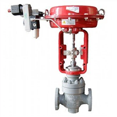
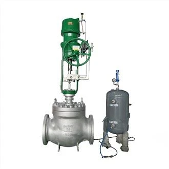
Handling abnormal position feedback signals of single-seat control valves
Leave a message
In industrial automation control systems, single seat control valves is a crucial actuators, which is responsible for controlling the flow rate, pressure and temperature of fluid medium accurately. Position feedback signal is the core basis of the control system to determine the actual opening degree of the control valve and realize closed-loop control. However, due to the complex field environment, equipment aging and improper installation and commissioning, abnormal position feedback signals have become common faults, seriously affecting the stability of the production process and product quality. This paper will systematically expound the performance, cause analysis, diagnosis and treatment of signal anomalies, and provide comprehensive technical guidance to engineers and technicians.
I. Common Manifestations of Abnormal Position Feedback Signals
1.1 Abnormal Signal Fluctuations
Under stable conditions, feedback signals from control valve positions fluctuate periodically or randomly, exceeding the normal range (usually ≤ ±1%). This fluctuation can cause the control system to adjust output frequently, cause actuator to oscillate and even damage the equipment. For example, in chemical production, a flow control loop with fluctuating feedback signals may lead to repeated opening and closing of control valve, which may lead to sudden changes in pipeline pressure and threaten system safety.
1.2 Signal deflection and Distortion
There is a certain deviation between the feedback signal and the actual position of the valve, which manifests the discrepancy between the display value and the actual opening. For example, the control system shows that the opening of the control valve opening is 50% per cent, whereas the actual opening is only 30 per cent. This deviation reduces control precision and causes product parameters to deviate from the set values. In particular, a substandard batch of products may be produced during precision machining or chemical reaction control.
1.3 Signal Interruption or loss of signal
Feedback signals disappear completely or are interrupted intermittently, preventing the control system from obtaining the actual position of the control valve. This may trigger a safety interlock action or put the system into open-loop control mode. In key areas, such as nuclear power plants, such failures can lead to emergency shutdowns and significant economic losses.
1.4 Signal Nonlinearity
There is a nonlinear relationship between the feedback signal and the position of the valve. For example, with the increase of valve opening, the signal increment decreases gradually. This characteristic destroys the linear compensation function of the control system and reduces the adjustment quality, especially in the case of variable load.
ii. Analysis on the Causes of Abnormal Position Feedback Signals
2.1 Mechanical Structure Factors
Valve Stem Jamming: Particles, scaling or insufficient lubrication in the medium may cause the stem to move slowly, preventing feedback devices from accurately tracking changes in valve position changes.
Transmission Components wear: gear, connecting rod and other transmission mechanisms wear or clearance too much, will cause mechanical lag and error, affect the accuracy of the signal.
Improper Installation of Feedback Devices: position sensors installation position deviation, fixed bolt loosening or coupling clearances too large, will lead to signal acquisition distortion.
2.2 Power System Factors
Sensor Failures: Aging, poor contact or damage to potentiometers, encoders and other position sensors directly results in abnormal signals.
Signal Line Interference: power cables and signal cables parallel laying, lack of shielding measures, or poor grounding, can cause electromagnetic interference, causing signal fluctuations.
Power supply Issuess: Unstable supply voltage, excessive ripple or failure of power module failures may affect the normal operation of sensor.
Controller Failures: Damage to input modules or incorrect parameter settings in phase-locked loops, DCS, and other control devices can lead to signal processing anomalies.
2.3 Environmental Factors
Temperature Effects: Extreme temperature may cause sensor materials to expand or contract, altering signal output characteristics. In northern winter, for example, control valves installed outdoors may reduce sensor sensitivity due to low temperatures.
Humidity and corrosion: High humidity or corrosive environments can corrode electronic components, causing short circuits or contact failures.
Vibration and impact: Mechanical vibration may loosen sensor mountings or damage internal components, especially in heavy industries such as metallurgy and mining.
2.4 Human Factors
Improper Maintenance: Failure to regularly clean, lubricate or calibrate feedback devices can accelerate equipment aging.
Operational Errors: Incorrect adjustments of sensor zero or span may result in signal baseline offsets.
Installation and debugging defects: A potential fault risks may arise if strict calibration or signal calibration is not performed during initial installation.
III. Diagnostic Methods for Abnormal Position Feedback Signals
3.1 Visual Inspection Methods
Observe operation status: check whether control valve is running smoothly and there is no abnormal noise.
Inspect Mechanical Connections: Make sure valve stem is firmly connected to the feedback device and the transmission components are not loose or worn.
Check the environmental condition: Examine the equipment environment for high temperature, humidity, vibration, etc..
3.2 Electrical Testing Methods
Signal Measurement: The voltage, current, or pulse waveform of a feedback signal is measured using a a multimeter or oscilloscope and compared with normal values.
Line detection: Test the insulation resistance of signal line and check if the line is short-circuited or open.
Power testing: Verify that supply voltage is stable and the ripple coefficient meets requirements.
3.3 Substitution Method
Sensor Replacement: Replace suspect sensors with backup sensors to observe if the signal returns to normal.
Controller test: Connect the feedback signal to another controller or analog input device to verify that the signal itself is working.
3.4 Trend Analysis
Historical data comparison: retrieving historical data from control system, analyzing the timing patterns of signal anomaly and its correlation to the change of running condition.
Spectrum analysis: Spectrum analysis of wave signals is performed to determine the frequency characteristics of interference sources and to assist in the identification of fault points.
IV. INTRODUCTION Treatment of abnormal position warning signals
4.1 Mechanical Fault Handling
Cleaning and lubrication: Wash valve stem and transmission components regularly and apply appropriate amount of grease to reduce frictional resistance.
Adjust and tighten: Reposition feedback device, tighten all connection bolts, eliminate gaps.
Replacement of Worn Parts: replacement of badly worn gears, connecting rods and other components to restore mechanical transmission accuracy.
4.2 Electrical System Maintenance
Sensor Maintenance: Clean potentiometer contacts, replacing encoders, or repairing signal processing circuits.
Line Rectification: using shielded double winch to separate relay signal cables to ground, so that it is away from power cables.
Power Supply Optimization: Install voltage stabilizers or filters to suppress voltage fluctuations and electromagnetic interference.
Controller Configuration: Check and correct input module parameters to ensure they match sensor specifications.
4.3 Environmental Improvement Measures
Temperature control: Install insulation or cooling devices in extreme temperature environments to maintain the equipment operating at a stable temperature.
Protection Upgrades: Seal equipment in damp or corrosive environment, choose corrosion resistant material.
Vibration Reduction Installation: Use vibration absorbers or rubber pads near vibration sources to reduce the impact of mechanical vibration.
4.4 Maintenance and Management Optimization
Develop maintenance plan: establish preventive maintenance system, clean, lubricate and calibrate regularly.
Operator training: to strengthen the operator feedback device working principle and maintenance key training, to avoid operational errors.
Spare Parts management: Storage of critical spare parts to shorten fault repair time.
Digital Monitoring: the introduction of intelligent diagnostic system, real-time monitoring of feedback signal status, early warning of possible failures.
V. Case Study
Case background
In the steam flow control loop of chemical plant, the position feedback signal of single seat control valve fluctuates periodically, which leads to the instability flow control and the decrease of product pass rate.
Diagnosis process
Preliminary inspection: control valve running smoothly, no blockage, eliminate mechanical blockage.
Electrical test: feedback signal voltage, fluctuation frequency and field frequency converters work frequency match, preliminary electromagnetic interference.
Line Inspection: Signal cable was found to be laid parallel to the frequency converter's power cable and not shielded.
Substitution Verification: after replacing signal cable with shielded double winch wire and grounding separately, the fluctuation disappeared.
Treatment measures
Signal cables are relayed with shielded twine and placed in separate pipes.
A magnetic ring filter is installed at the input end of the signal to further suppress high-frequency interference.
Complete cable laying specification and specify the spacing requirement between power cable and signal cables.
Effect Verification
After processing, the feedback signal is stable, flow control accuracy returned to design requirement, and product pass rate is obviously improved.
VI. INTRODUCTION Conclusion:
Single-seat control valves Abnormal position feedback signals is a common complex fault in industrial control system, which involves mechanical, electrical, environmental and human factors. The combination of system diagnosis with preventive maintenance and intelligent management can effectively reduce the occurrence of such faults and ensure the long-term stability of production process. In the future, predictive maintenance based on condition monitoring will be a key direction to address these issues with the development of technologies such as the Internet of Things (IoT) and big data, providing more reliable technical support for industrial automation control.